Circuit Diagram Symbols
Application Name:
File Type = .Exe
Credit To @ pinterest.com
PDF Download
Open new tab

Application Name: Electrical Schematic Symbols Electrical schematic
File Type = .Exe
Credit To @ www.pinterest.com
PDF Download
Open new tab

Application Name: Some of the symbols that you would need to familiarize
File Type = .Exe
Credit To @ www.pinterest.com
PDF Download
Open new tab

Application Name: Electrical Schematic Symbols (With images) Electrical
File Type = .Exe
Credit To @ www.pinterest.com
PDF Download
Open new tab

Application Name: Wiring Diagrams Symbols
File Type = .Exe
Credit To @ www.pinterest.com
PDF Download
Open new tab

Application Name: HOW TO READ CIRCUIT DIAGRAMS Circuit diagram, Circuit
File Type = .Exe
Credit To @ www.pinterest.com
PDF Download
Open new tab
Scan through and easily download the one you need.

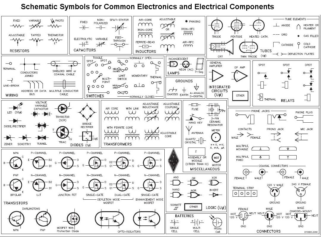
Circuit diagram symbols. Electrical symbols & electronic circuit symbols of schematic diagram - resistor, capacitor, inductor, relay, switch, wire, ground, diode, LED, transistor, power. Voltage monitoring circuit for 12 volt lipo battery pack schematic circuit diagram may 25, 2020 Simple led circuits led projects schematic circuit diagram may 26, 2020; Most of the industrial standard circuit items can be changed in the.
The symbol for a thermal fuse used in any electrical circuit diagram. To build a circuit you need a different diagram showing the layout of the parts on breadboard (for temporary circuits), stripboard or printed circuit board. A fixed resistor has a resistance. Standard Circuit Symbols For Circuit Schematic Diagrams.
A resistor restricts or limits the flow of electrical current. Circuit diagrams can be created with thousands of possible shapes and icons and Lucidchart’s circuit diagram maker has all the bells and whistles to ensure you have everything you need to create an industry-standard diagram. Think of what we usually call a single battery. Important updated version regularly and free too.
950mhz 2000mhz analog satellite finder schematic circuit diagram may 28, 2020; They are mostly used to draw a circuit diagram and are standardized internationally by the IEEE standard (IEEE Std 315) and the British Standard (BS 3939). Electrician Circuit Drawings and Wiring Diagrams Youth Explore Trades Skills 3 Pictorial diagram: Design circuits online in your browser or using the desktop application..
Circuit symbols are used in circuit schematic diagrams which show how a circuit is connected together electrically. This article gives some of the frequently used symbols for drawing the circuits. To build a circuit you need a different diagram showing the layout of the parts on stripboard or printed circuit board. The symbol for a battery is shown below.
Berry All the symbols you need to design your pneumatic circuit in .dxf format. It shows the relative positions of all the elements and their connections to one another. Circuit Diagram is a free application for making electronic circuit diagrams and exporting them as images. Pneumatic Symbols Only when the design fails does it draw attention to itself;
An electronic symbol is a pictogram used to represent various electrical and electronic devices or functions, such as wires, batteries, resistors, and transistors, in a schematic diagram of an electrical or electronic circuit.These symbols are largely standardized internationally today, but may vary from country to country, or engineering discipline, based on traditional conventions. When it succeeds, it’s invisible. We use circuit symbols to draw diagrams of electrical circuits, with straight lines to show the wires. Here is an overview of the most used symbols in circuit diagrams.
Circuit Diagrams Circuit symbols are used in circuit diagrams which show how a circuit is connected together. See more ideas about Electrical diagram, Electrical circuit diagram, Electrical engineering. In electronic circuits, there are many electronic symbols that are used to represent or identify a basic electronic or electrical device. It operates on the temperature rather than the current unless the current is sufficient to increase the temperature above the threshold point.
Circuit symbols are used in circuit diagrams showing how a circuit is connected together. A diagram that represents the elements of a system using abstract, graphic drawings or realistic pictures. The purpose of the circuits diagram is to help electricians and engineers gain a detailed understanding of how the circuit works instantly. Another means of describing a circuit is to simply draw it.
A large and a small line is suppose to represent one battery cell so that the image below would suggest a two-cell battery of 3 V. To be able to read schematics you must know the schematic symbols. Feb 5, 2020 - Explore elects59's board "Electrical diagram" on Pinterest. This enables anyone to read a circuit diagram and know what it does relatively quickly.
Synchronizing transistors schematic circuit diagram may 27, 2020; For example, C1 is the first capacitor, L1 is the first inductor, Q1 is the first transistor, and R1 is the first resistor.

Application Name: Schematic, also called circuit diagram, is to show how
File Type = .Exe
Credit To @ www.pinterest.com
PDF Download
Open new tab
