Circuit Diagram Starter Motor

Application Name: 1000+ images about 3 phase on Pinterest Electrical work
File Type = .Exe
Credit To @ www.pinterest.com
PDF Download
Open new tab

Application Name: Starter motor, starting system how it works, problems
File Type = .Exe
Credit To @ www.pinterest.com
PDF Download
Open new tab

Application Name: Image result for suzuki multicab electrical wiring diagram
File Type = .Exe
Credit To @ www.pinterest.com
PDF Download
Open new tab

Application Name: When heavy motor systems or high current motors are
File Type = .Exe
Credit To @ www.pinterest.com
PDF Download
Open new tab

Application Name: Motor Control Center Wiring Diagram Electrical
File Type = .Exe
Credit To @ www.pinterest.com
PDF Download
Open new tab

Application Name: How To Wire A Room In House Diagram, Electrical circuit
File Type = .Exe
Credit To @ www.pinterest.com
PDF Download
Open new tab
It’s easy to obtain perplexed concerning electrical wiring representations and also schematics.

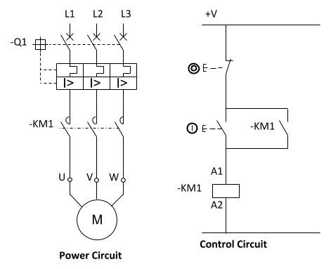
Circuit diagram starter motor. The main function of car starting circuit is using the small current from the car battery to control the large current of the car starting circuit, thus to start the starter motor and power the engine. A star delta starter is a type of reduced voltage starter.We use it to reduce the starting current of the motor without using any external device or apparatus. Between the mains supply terminals and motor terminals the DOL starter main terminals are connected and with the two terminals of the three-phase power supply as described in figure (1) the control circuit is energized. What is DOL Starter.
A DOL starter (or Direct On Line starter or across the line starter) is a method of starting of a 3 phase induction motor.In DOL Starter an induction motor is connected directly across its 3-phase supply, and the DOL starter applies the full line voltage to the motor terminals. The coil of the motor starter can be de-energized several ways. The stop pushbutton can be pressed removing power from the seal-in contact causing the coil to be de-energized. The following schematic illustrates the Yamaha XS650 Starting System Circuit and Wiring Diagram.
The Direct On Line Starter Method figure is shown below. Electrical wiring layouts mostly shows the physical position of elements and links in the constructed circuit, yet not necessarily in reasoning order. If you have a 120V coil, instead of running a line from Coil - Overload - L2, you must run Coil - Overload - Neutral. The Direct On Line Motor Starter (DOL) consist a MCCB or Circuit Breaker, Contactor and an overload relay for protection.
44 Best Motor Starter Circuit Diagram. When motor starter #1 energizes, the normally open auxiliary contact 1M closes, providing power to coil 1M and to push button #2. Variety of 3 phase motor starter wiring diagram. Assortment of 3 phase motor starter wiring diagram pdf.
It shows the parts of the circuit as simplified shapes, and also the power and also signal links in between the tools. V motor starter wiring diagram together with volt 3 phase wiring diagram besides along with wiring diagram view contactor start stop along with how. A wiring diagram is a simplified standard photographic depiction of an electric circuit. In this tutorial, we will show the Star-Delta (Y-Δ) 3-phase induction AC Motor Starting Method by Automatic star-delta starter with Timer with schematic, power, control and wiring diagram as well as how star-delta starter works and their applications with advantages and disadvantages.
If the starter does not turn the engine although the car battery is in good condition, the fault may be a simple mechanical one or it may be an electrical one in the starter-motor circuit. Colorful Eaton Motor Starter Wiring Diagram Illustration. In this instance, the starting circuit cut-off relay is off so current can not reach the starter motor. Four-point manual DC motor starter circuit diagram.
Star-Delta (Y-Δ) 3-phase Motor Starting Method by Automatic star-delta starter with Timer. Ignition switch, starter solenoid, starter relay. The motor is connected through a starter across the full supply voltage. The starter system is simple, and the checks on it are straightforward.
A mechanical check to see if the starter pinion gear. (click image to enlarge) The starting circuit cut-off relay prevents the starter from operating when neither of these conditions has been met. Electrical checks are made with a circuit tester or test lamp or with a voltmeter. The simplest form of motor starter for the induction motor is the Direct On Line starter.
M A1 A2 M. Circuit diagrams Wye-delta Wye-delta, open transition – STOP-START The wye-delta open transition starter starts the motor by closing the S and 1M contactors which energize the windings in wye. It reveals the elements of the circuit as streamlined forms, and the power and signal connections between the tools. How dol starter control diagram works.
The motor could go into overload which means the normally closed overload contacts will open breaking the circuit. The star contactor serves to initially short the secondary terminal of the motor U2, V2, W2 for the start sequence during the initial run of the motor from standstill. In this circuit, the load will always be on unless power is lost to the entire control circuit because either the single pole switch could be the activating factor or at any given moment the liquid level switch could energize the coil of the motor starter in the control circuit. (i) DOL starter wiring connection with start and stop buttons are shown in the above figure (1).
In effect, there are four states: FIBER OPTIC CABLE ELECTRICAL CONNECTIONS MOTOR 3CT TO V SEPARATE CONTROL * OT is a switch that opens when an overtemperature condition exists (Type MFO and MGO only) T1 T3 WIRING DIAGRAM. Despite this direct connection, no harm is done to the motor. Electric circuit, electrical circuits, circuit diagram, electrical symbols, circuit diagrams, electrical circuit diagram, electrical wiring diagrams, motor control circuit diagram, star delta wiring diagram, star delta control diagram, star delta starter circuit diagram, star and delta connection, delta connection, delta connect, motor control diagram, motor control circuit diagram, contactor.
Power circuit of Star-Delta starter. Three Phase Motor Power & Control Wiring Diagrams Three Phase Motor Connection Schematic, Power and Control Wiring Installation Diagrams. Figure 4 shows the automatic DC starter circuit diagram. One design that will meet the requirements is shown in Figure 31 – 1.
Cutler Hammer Starter Wiring Diagram Elegant 3tf5222 0d Contactors. In this circuit, push button #1 must be pressed before power can be provided to push but- ton #2. An automatic starter operates in a similar fashion, except that automatic relays short out sections of the starter resistance either by a time sequence or when the armature current drops to a selected value. It consists a coil operated contactor C controlled by start and stop push button as shown in the connection diagram below.
Application Name: Pinterest • The world’s catalog of ideas
File Type = .Exe
Credit To @ www.pinterest.com
PDF Download
Open new tab
